Hi guys!,
This third entry about the build a DIY Powerwall, we are going to make the first battery pack assembly. As we discussed above, we will use 18650 Chinese (aliexpress) cells, Liitokala’s NCR18650B cells.
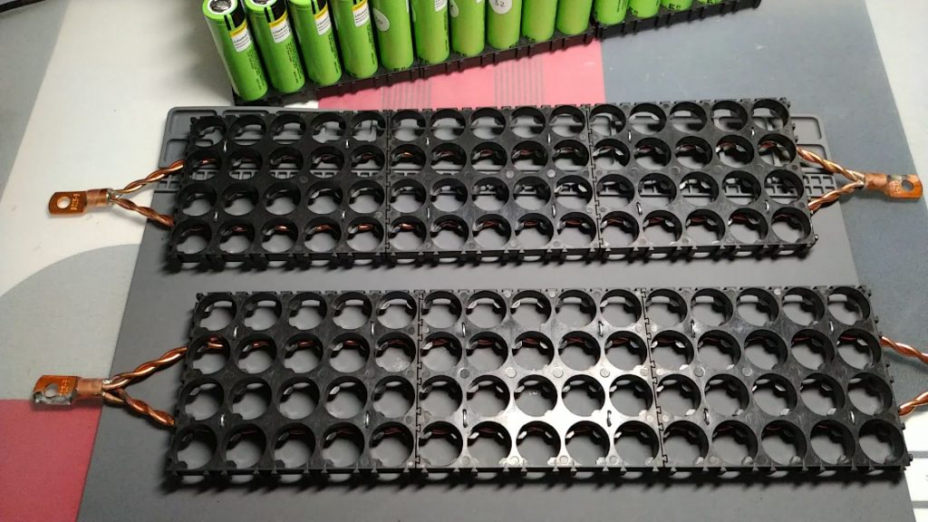
If you have not seen the previous entries, I recommend it, as we explain how to check the cells before moving on to their assembly and how to prepare the supports for the cells. You can access through the link DIY Powerwall #1 (testing cells) and DIY Powerwall #2 (prepare holders).
Assembling the first pack of cells
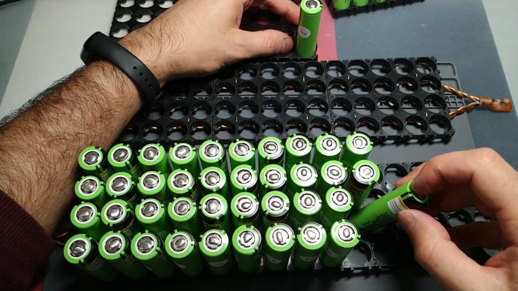
The first step will be to insert the cells into the holders. Remember, these are cells we’ve checked before. It is very important that you do, as a faulty cell could ruin the pack. I leave you photos:
Welding cells 18650 to bus bar
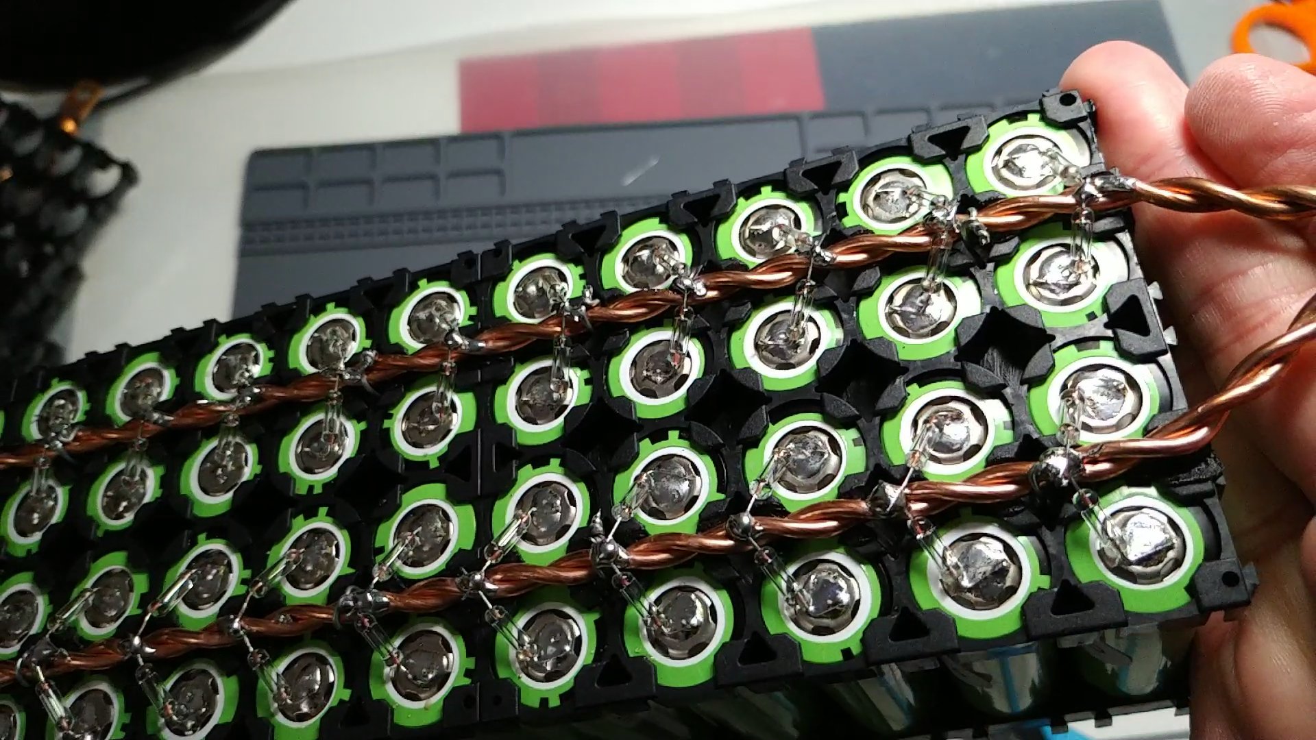
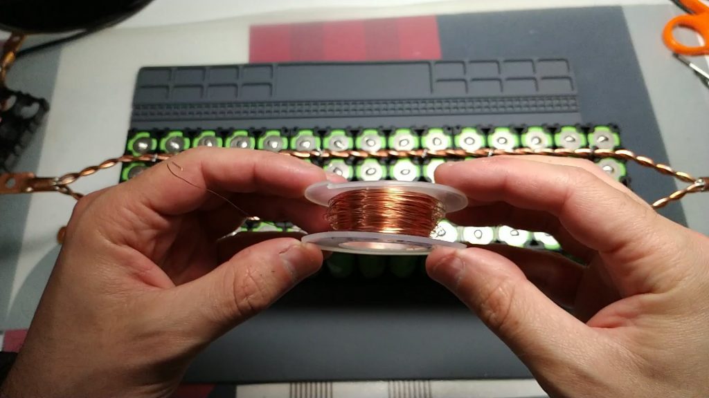
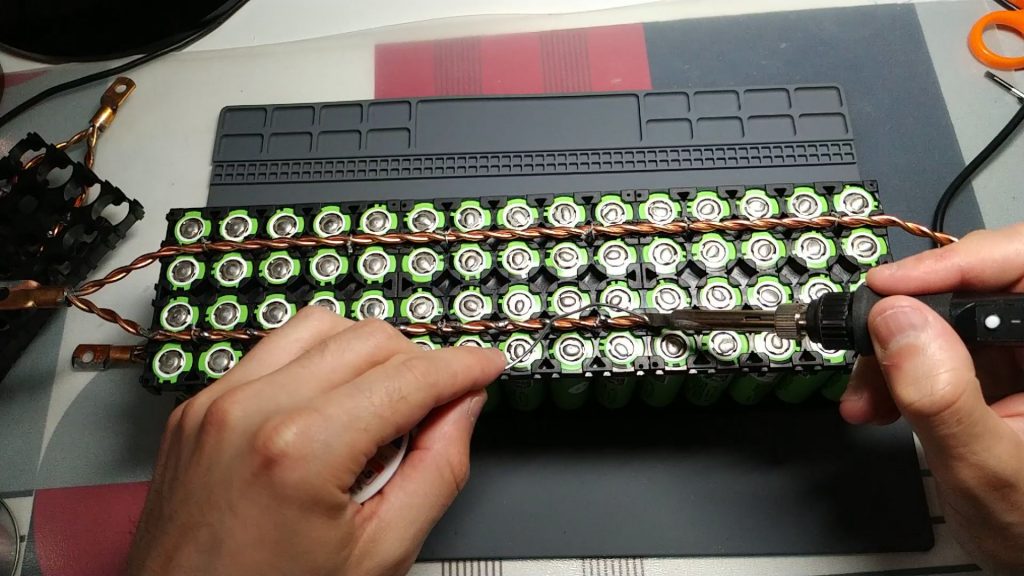
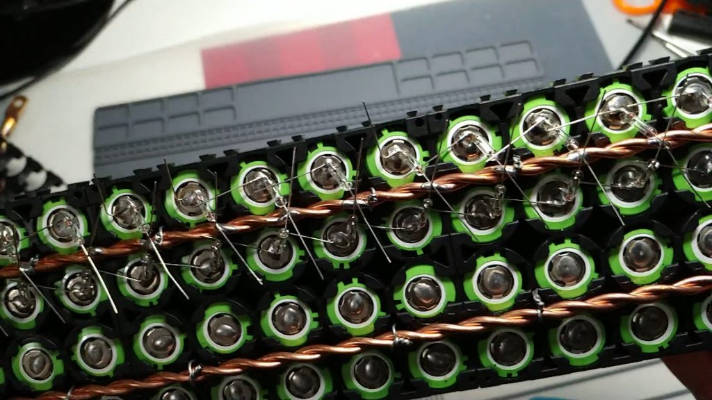
The next step will be to weld the cells at both poles to the bus bar. After several tests, I have decided to use 5A glass fuses for the positive pole, and 0.3mm enamelless copper wire for the negative pole. I’ll leave you some pictures:
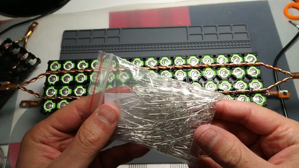
- I leave you the links where I bought the glass fuses: buy 5A glass fuses
- And the link where I bought the 0.3mm enamel-free copper wire: buy 0.3mm copper wire without enamel
I’ve tested both components and the copper wire can withstand more intensity than 5A fuses, so in principle it should never act as a fuse. However, if a fuse is defective and does not blow, it could act as a fuse, adding more security to the system, which is never left over.
I have also checked the temperature of the fuses and the wire depending on the intensity that passes through them. Up to 3A nothing heats up, so we won’t be losing energy in the form of heat. From this intensity if they start to heat up so it would not be very efficient. In our case, as we calculated in the previous entry, a maximum of 1.7A will be extracted from each cell, so the system will not be heated at any time. All this, as I have already commented on in the other entries, it is necessary to calculate it for each particular case, taking into account both the capacity of the powerwall, as well as the number of maximum watts that we consider to extract from it.
Why have I decided to use glass fuses and non-copper wire for the positive pole?
Because it always blow at the same intensity, it does not depend on many factors such as copper wire (the intensity it holds varies with the length of the wire, if it has any wrinkles, etc.). Another feature that I like the most is that with glass fuses if we make a short to a cell for example, melts instantly and does not get to heat anything, while the wire takes some time until it gets red hot and burns, it can melt some plastic pack (plus leaves residue, not like fuses).
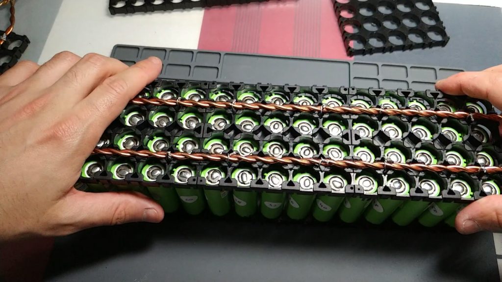
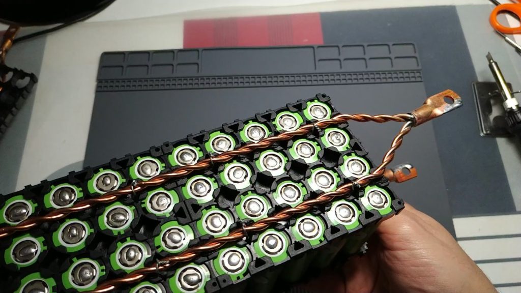
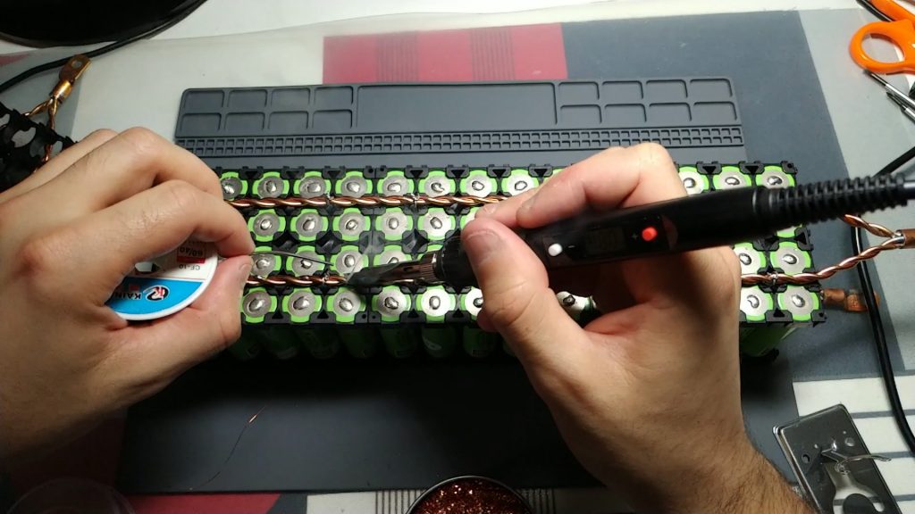
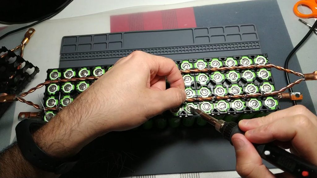
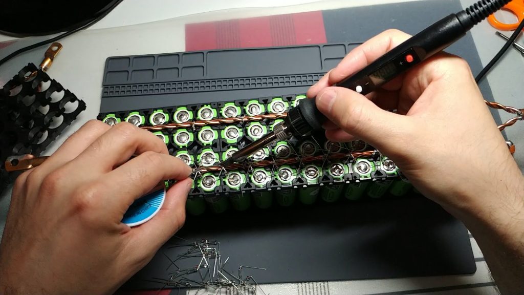
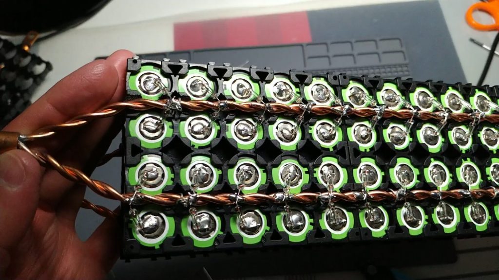
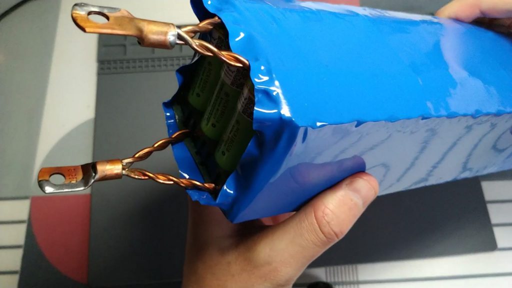
Let’s go on to explain the process of how I welded the cells. I started with the negative pole, where we’re going to weld the cells to the bar bus with the 0.3mm copper wire. First of all, what I do is apply some tin to the bus bar at the height of half the cells to later facilitate the soldering of the copper wire to the bus bar. I’ll leave you some pictures:
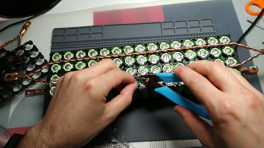
Then we weld the copper wire between each cell pair: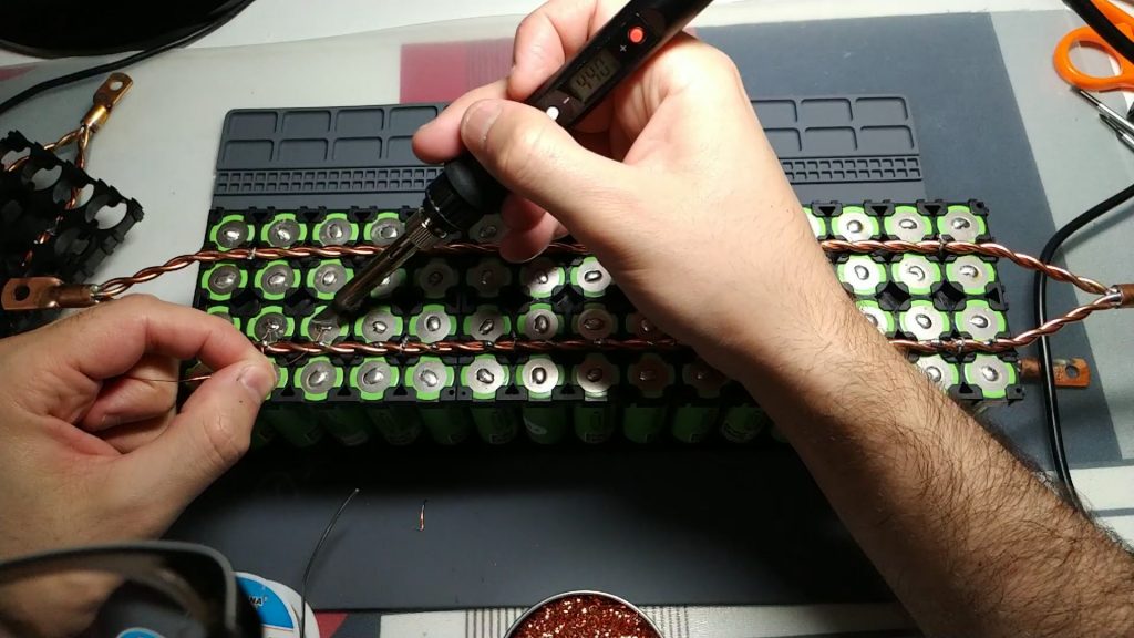
We weld the wire in the inner cell:
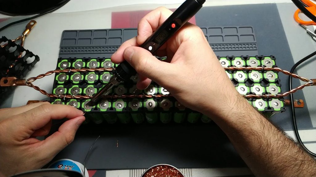
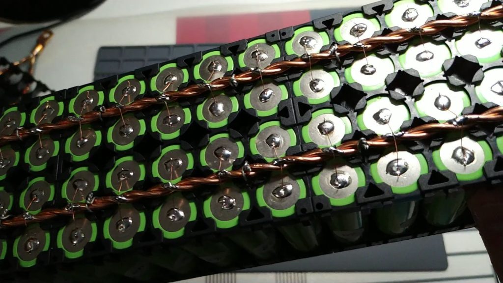
Once we have welded the wire into all the cells, we proceed to weld the wire to the bus bar:

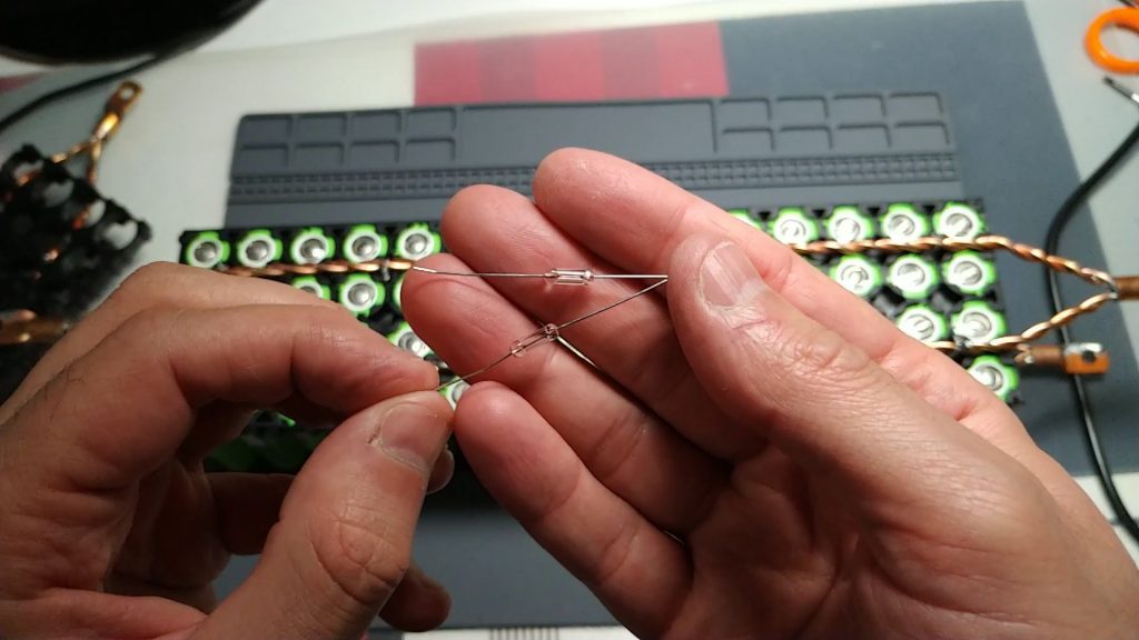
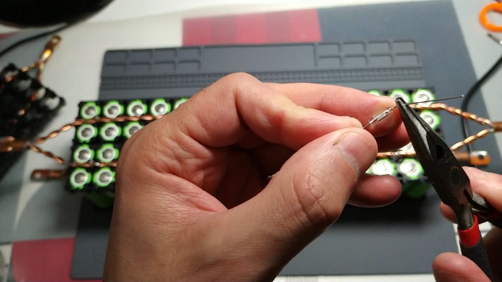
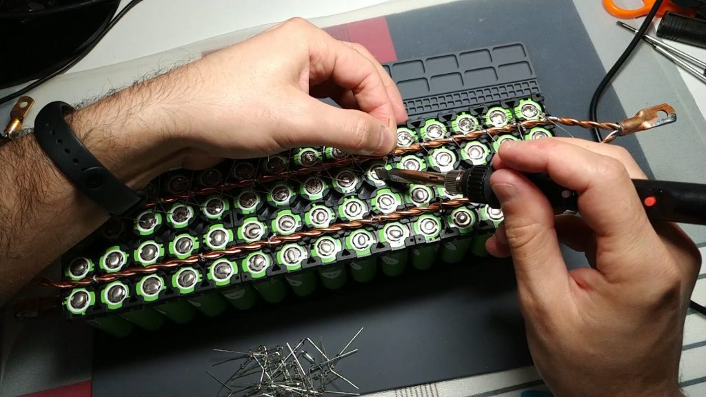
Now I move on to welding the positive pole of the cells. As we discussed above, in this case we will use the glass fuses. First of all I apply tin to the bus bar, as we did in the other holder, but this time I apply it at the height of the left edge of the cells, since the fuse is longer and must go sideways. Once the bus bar has been ready, we went on to prepare the fuses. Let’s bend one of the fuse legs 90 degrees with a pliers. We’ll bend it pretty attached to the fuse glass. Once we have everything ready we will go to weld them in the cells. You can see in the photos as I do:
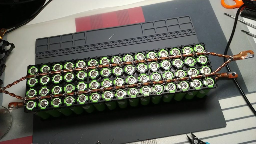

 Finally, we check with a polymeter that there is continuity between the poles of the cells and its bus bar. We do it at both poles and with all cells:
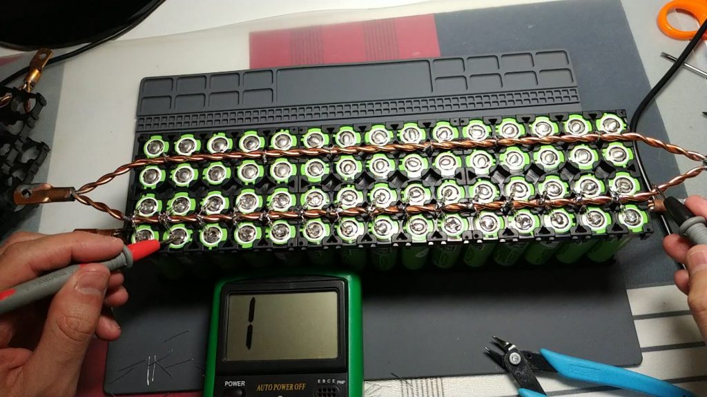 Check the continuity between the cells and the bus bar
Finish the powerwall pack
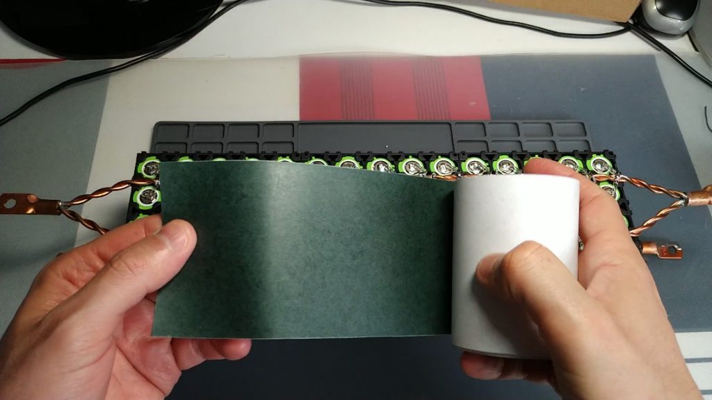
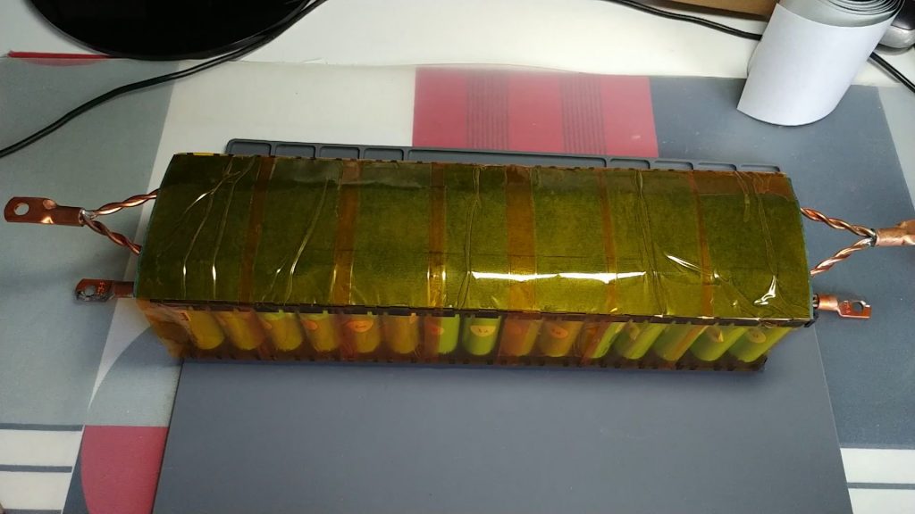
Finally, we’re going to add some protection to the pack, to prevent damage to any fuse or copper wire when we handle it.
First of all we will add an insulating that has a sticker on one side. I used the 80mm wide model.
- You can buy this insulating at the following link: buy 18650 80mm wide insulating
I’ll leave you some pictures:
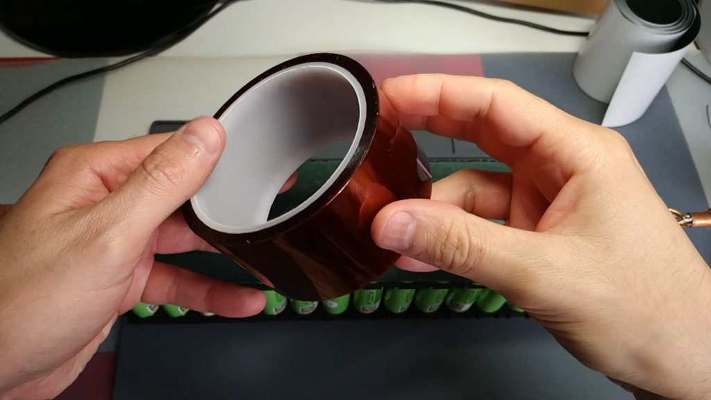
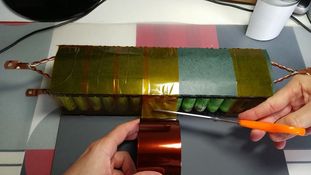
Once the insulating is glued, we will apply a special adhesive tape for electronics, which is also heat resistant. In my case I bought the 50mm wide model. This will keep us from moving the board we put in earlier.
- You can buy this adhesive tape at the following link: buy heat-resistant adhesive tape
I’ll leave you some pictures:
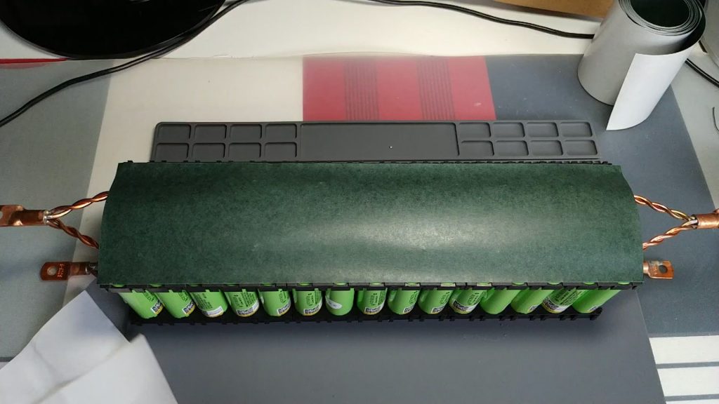
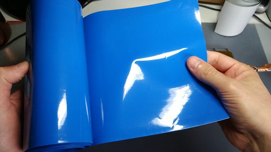
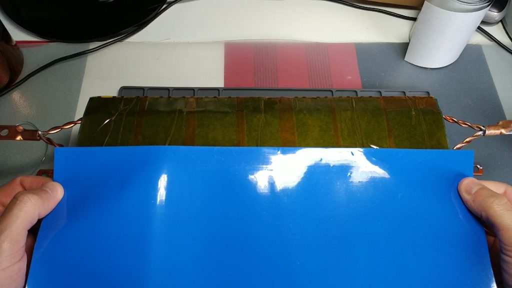
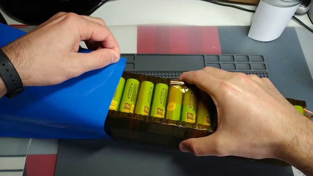
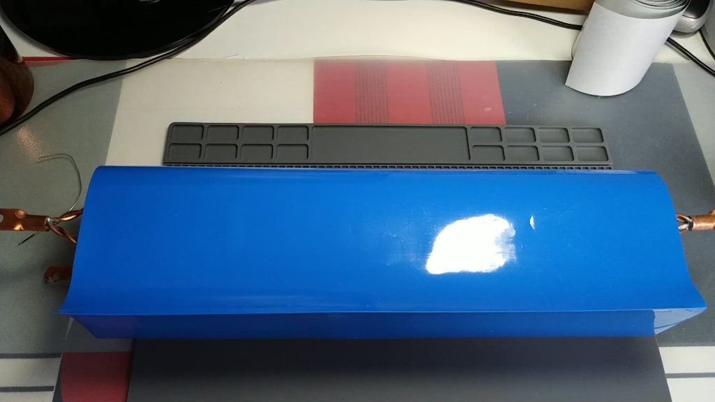
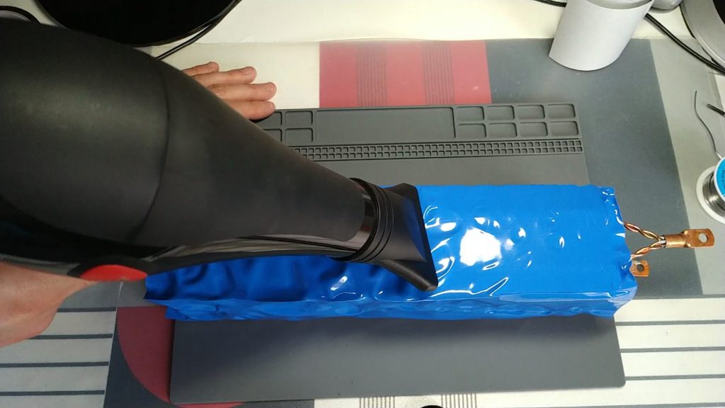
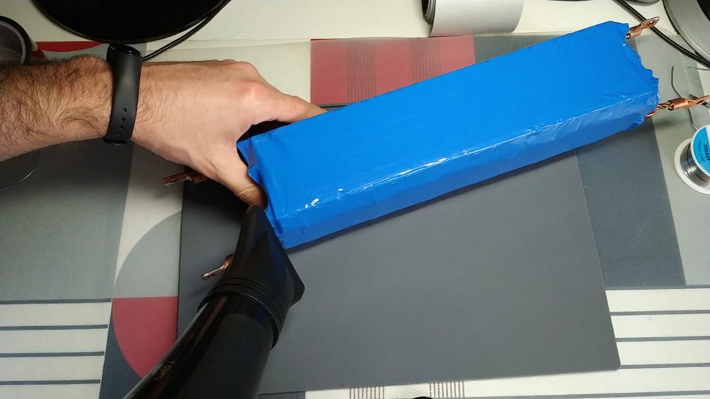
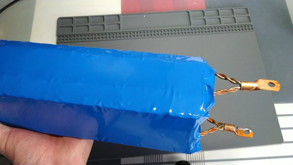
Finally we will add a shrink plastic to the pack. The size I bought is 180mm wide. This gives us a bonus of external protection that never badly. To apply heat, I used a hairdryer.
- You can buy this shrink cover at the following link: buy heat shrink cover
I’ll leave you some pictures:
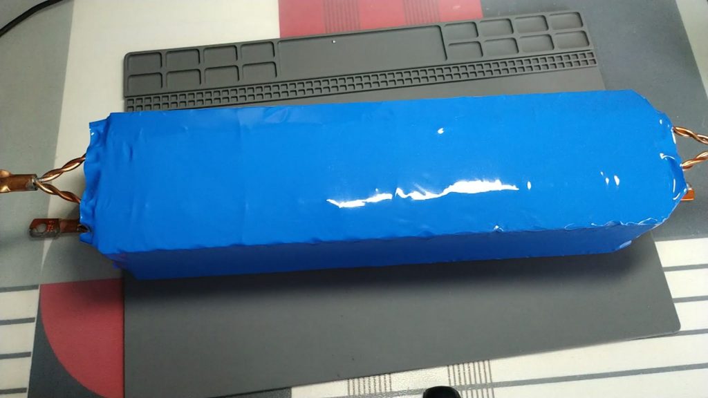
We already have our first pack of cells. Now you only need to do 13 more to complete the powerwall (almost nothing…).
In future entries I will show the rest of the packs, and how I will roll them.
I hope it will help you if you are considering doing something similar.
If you have any questions, you can leave it in comments.
Many thanks and greetings!
Nice project, I like the idea with the glass fuses. Looks like quality work, keep it up!
Thank you! Glass fuses work very well, and they weld relatively quickly. It is worth the work. At the moment I have 5 packs mounted. I am waiting for more cells to arrive (covid does not help…)