
Hi guys,
This second entry about the build a DIY Powerwall, we will prepare the holders on which we will mount the cells. As we discussed above, we will use 18650 Chinese (aliexpress) cells, Liitokala’s NCR18650B cells.
If you have not seen the previous entry, I recommend it, as we explain how to check the cells before moving on to their assembly. You can access it through the link DIY Powerwall #1 (testing cells).
Cell holder 18650
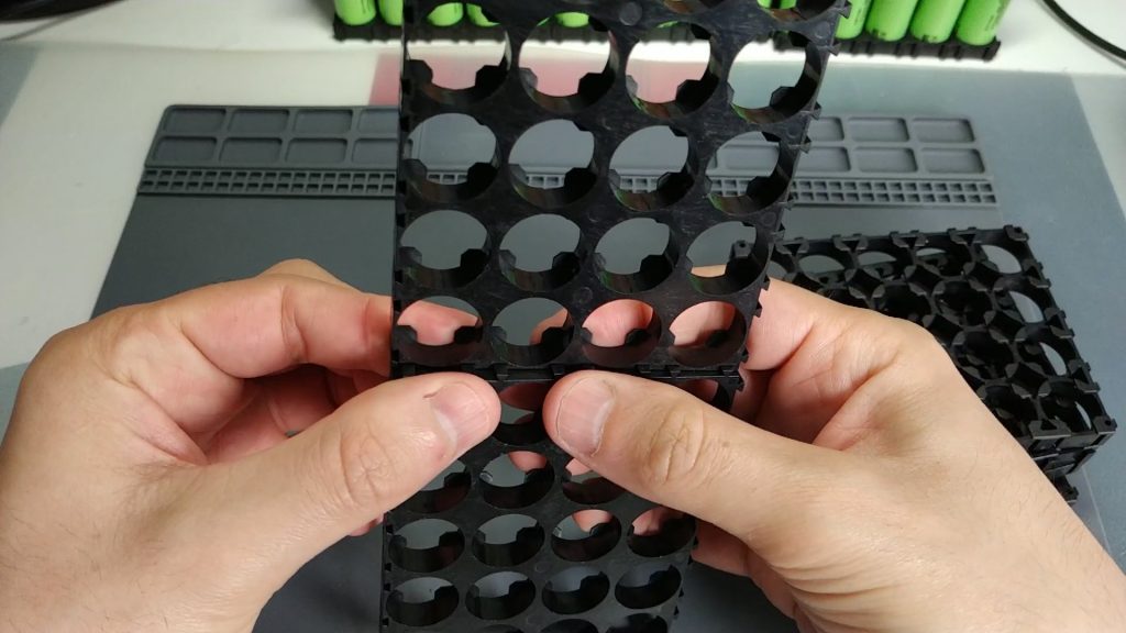
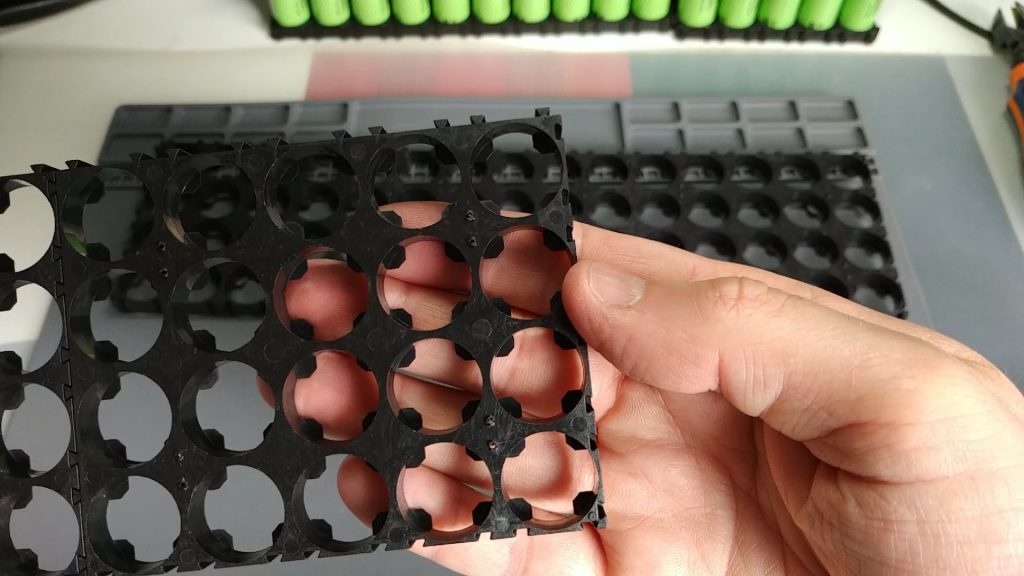
Let’s use some plastic holders that are 5×4 cells. These holders come prepared to be joined together, both lengthwise and wide. In our case, each pack of the powerwall will be 60 cells, so we will hook 3 holders. I’ll leave you some pictures:
You can buy these holders in the following link: buy holders 5×4 cells 18650
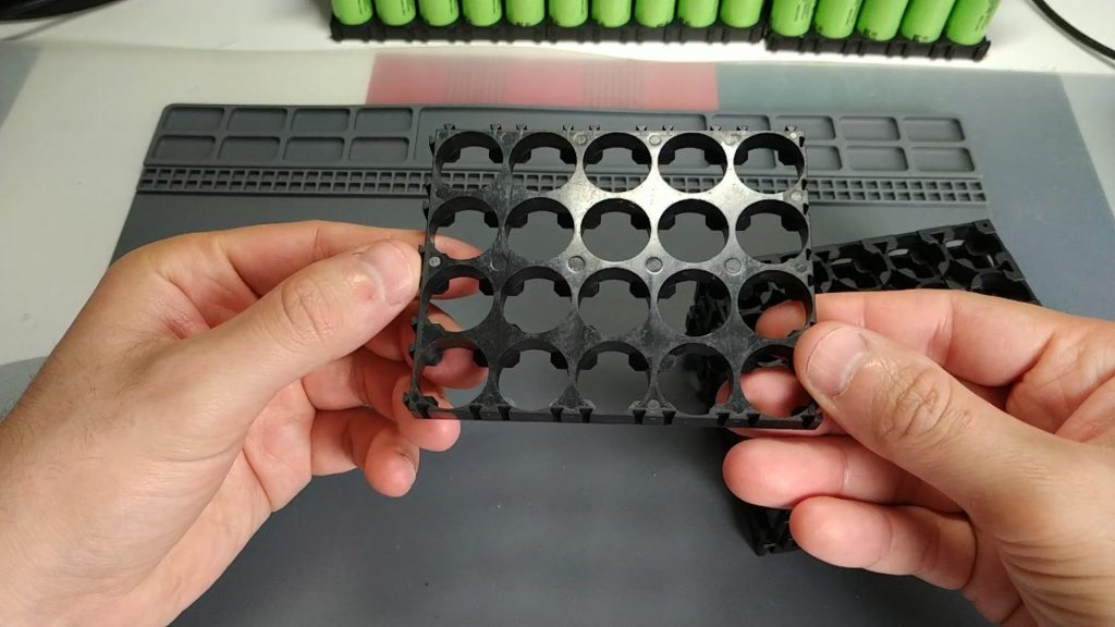
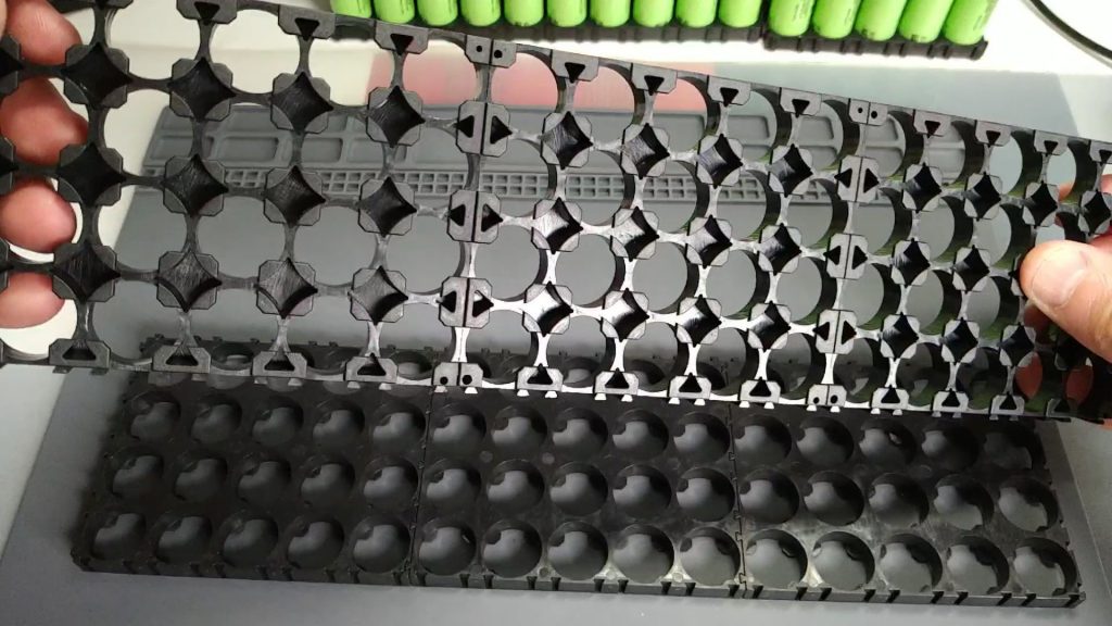
We need to make two 60 cell holders, one for each end of the cells.
Prepare cell holders 18650
The next step is to make a few small modifications to these holders to be able to fix the “bus bar” later, that is, the central copper cables to which we will connect all the cells. You can see them later.
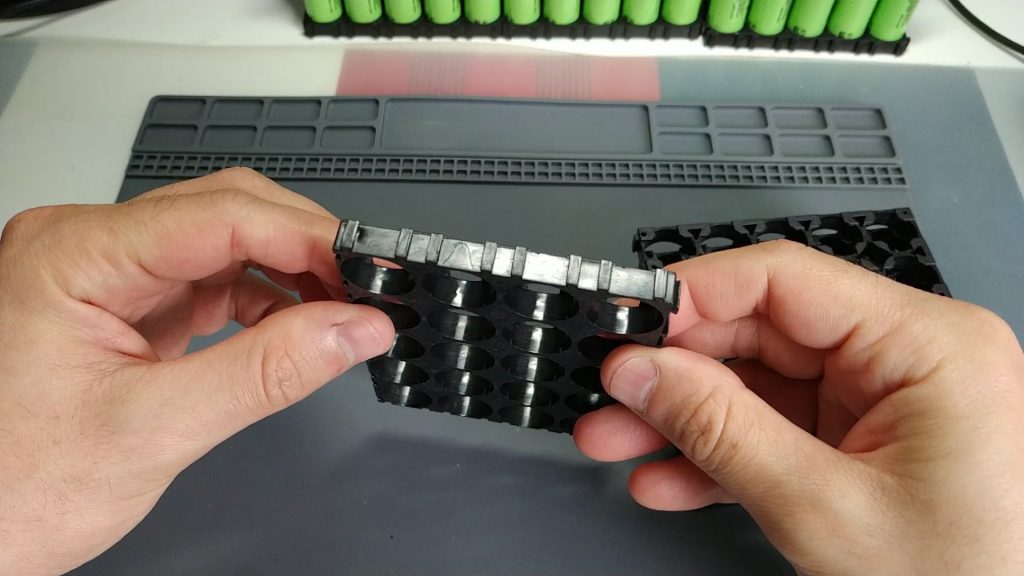
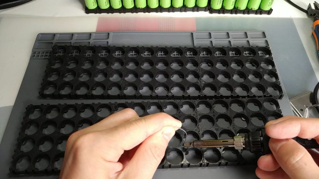
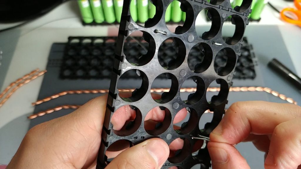
The first modification we will make is to make two small holes as seen in the photo. We’ll do them on the 3 holders we have attached. To make these holes I used a wire that I’ve heated with a tin welder. I put some photos where you can see it:
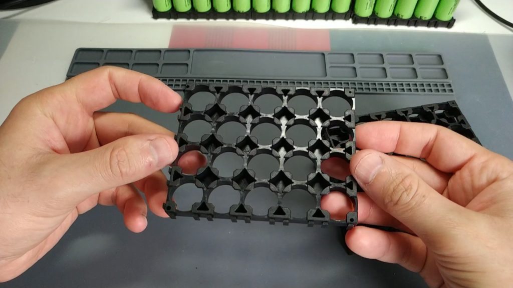
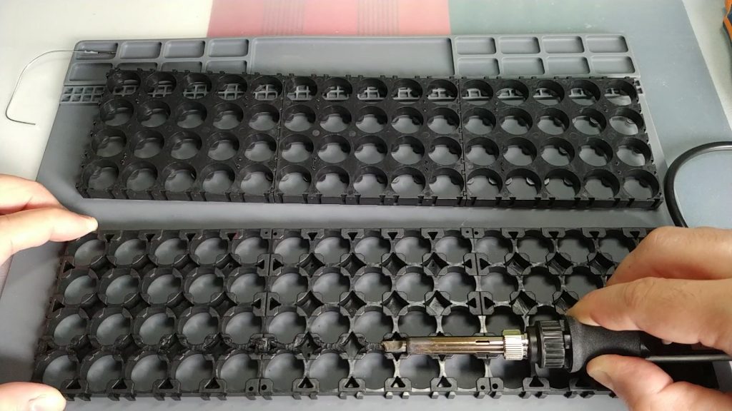
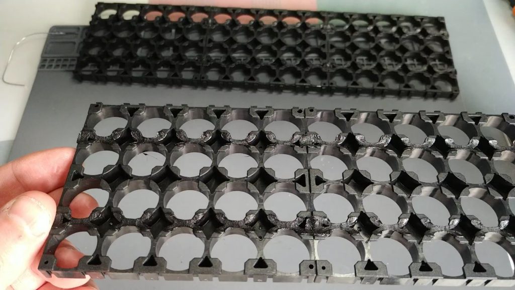
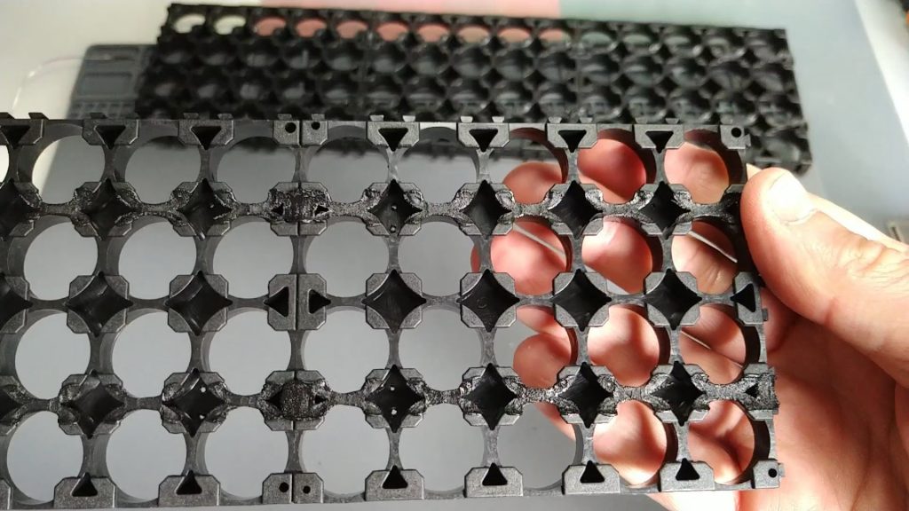
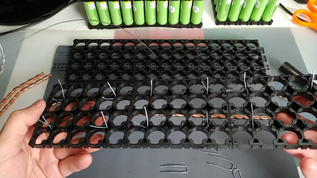
The next modification will be to make a small rail on the outside of the holders. This rail will help us to make the bus bar settle properly. It’ll be firmer and keep him from moving.
To make the rail I also use the tin welder. I slide it through the outside of the stand, so that it melts it a little and forms the rail. I don’t use the tip of the welder, but I do it with the thickest area of this. Be careful because this gives off a lot of smoke. I recommend doing it in a ventilated area. I’ll leave you some pictures:
Prepare the “bus bar”
To make the bus bar, we will use “naked” copper cable, that is, it has no outside protection. In my case, I bought in a hardware store 35mm2 copper cable, which consisted of 6 wires about 2mm in diameter each.
It depends on the power you want to load from the powerwall, it is necessary to calculate that amperage can reach to circulate through the bus bar. In my case, for example, I will be able to load up to 5000W of power. By making a small calculation, let’s look at amp stories this translates: 5000W / 48V = 104A. So we’ll need to support 104A in every powerwall pack.
Each copper wire is 2mm in diameter, and can hold 25A without problem (I have performed tests to check it and nothing is heated with that intensity). Therefore, if we use 2 wires for each bus bar, and put two bus bar for each pole of the pack, they could circulate the 104A we need. We will need to perform these calculations to adapt to the particular needs of each installation.
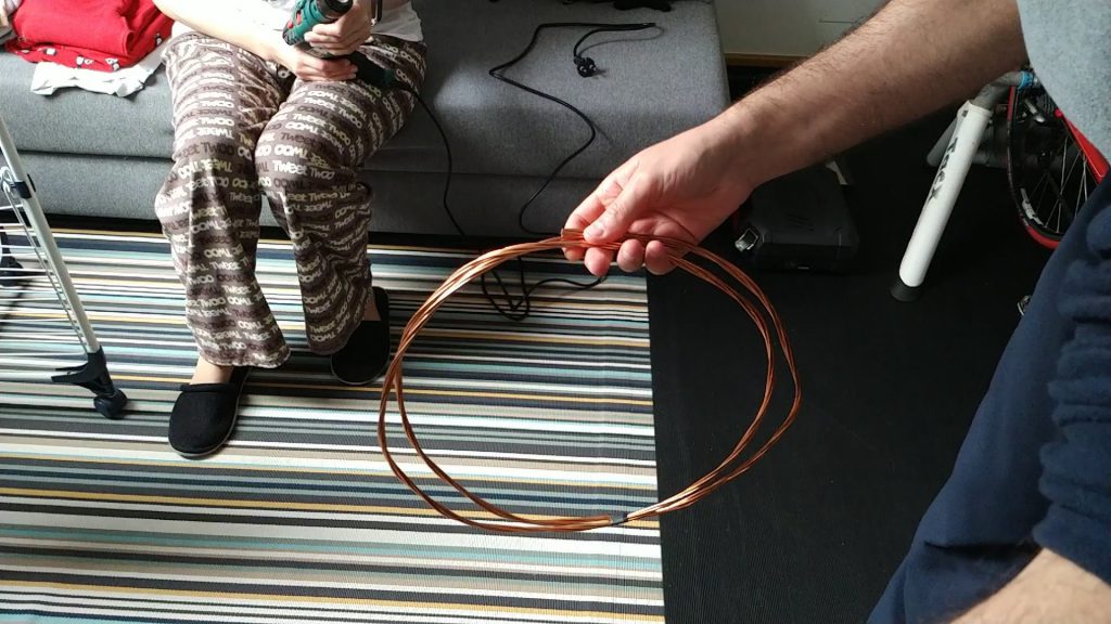
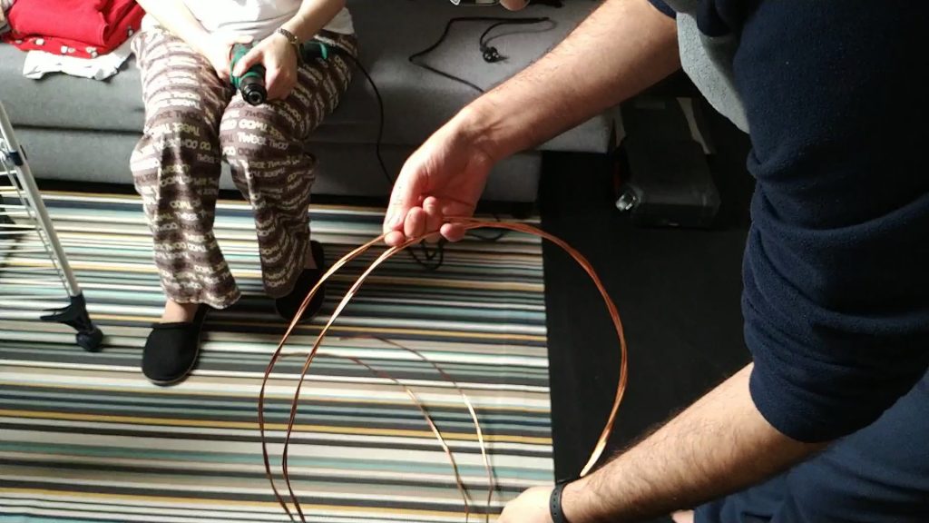
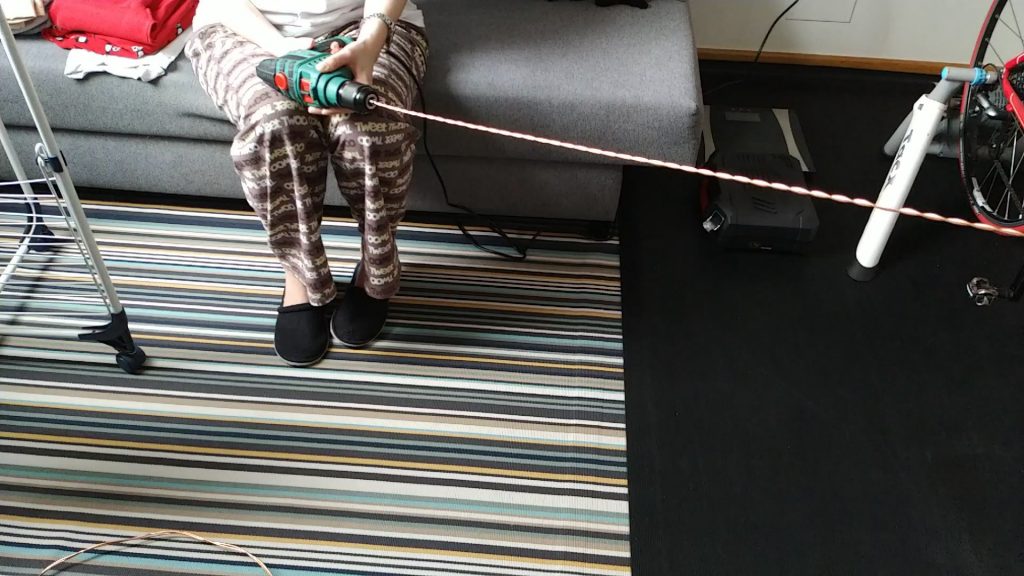
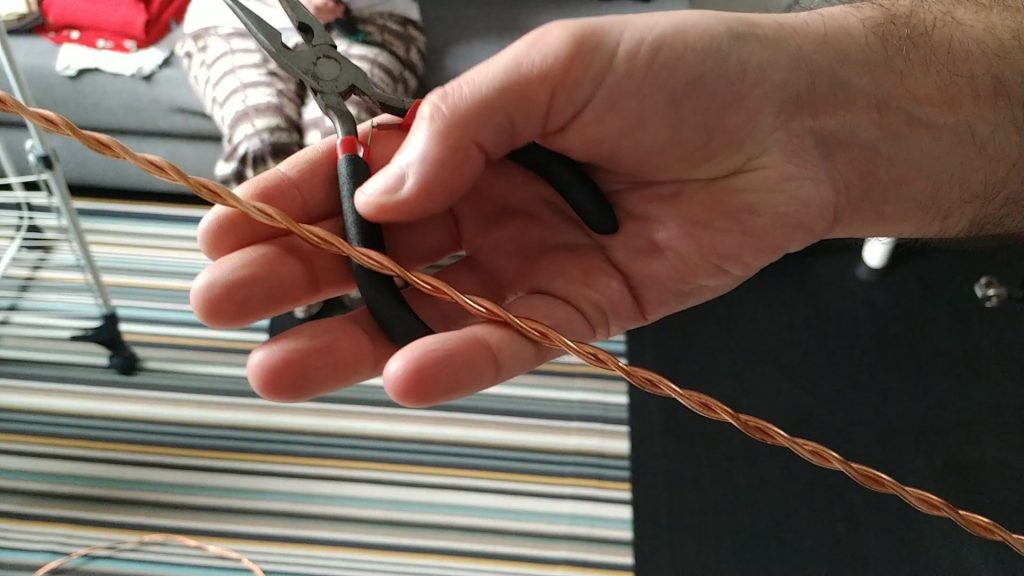
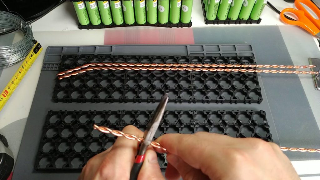
What we will therefore do will be to destrench the copper cable to extract 2 wires. These two wires, we will hook them with a drill at one end, and on the other we will hold it with a bench screw for example. It is important that it is an adjustable speed drill to go slowly. If you don’t have a bench screw (as is my case), you can do it between two people, one grabbing the drill and one at the other end grabbing with some pliers (that’s how I did it). You’ve got to roll it up enough to make it well consistent. I leave you some photos so that you see how it looks:
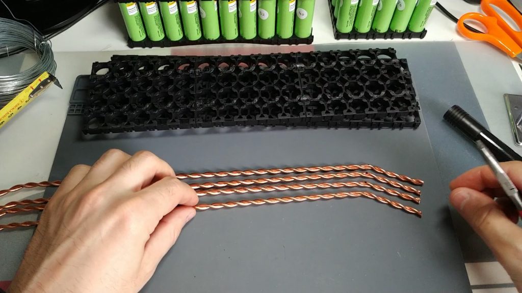
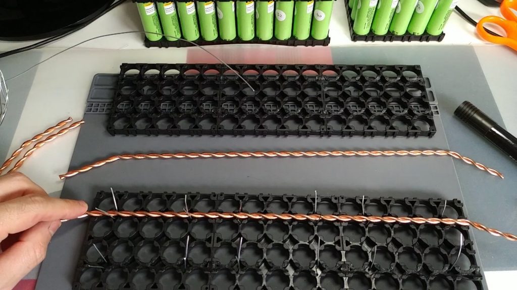
I used a length of 2 meters, since then we will cut it in sections of 40cm. So it would give us to make 5 bus bar. I leave you some photos of the bus bars already cut off:
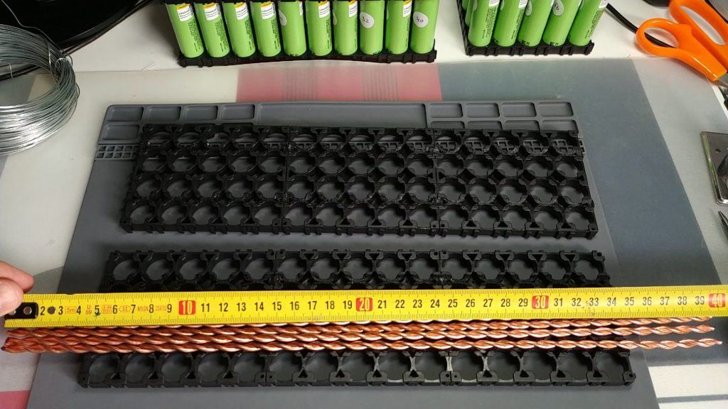
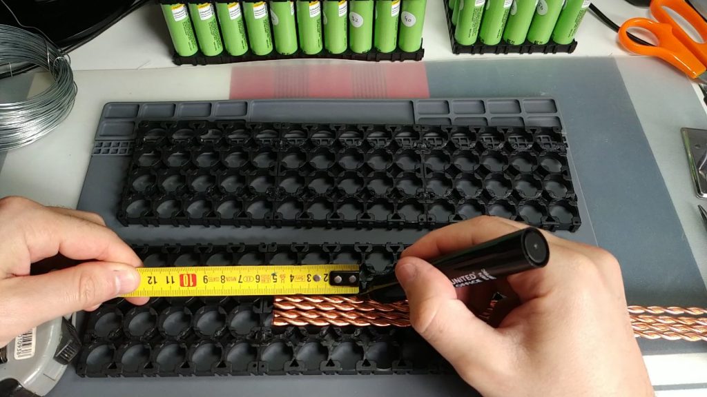
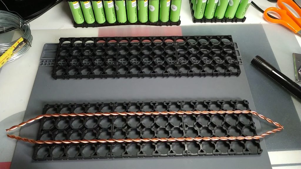
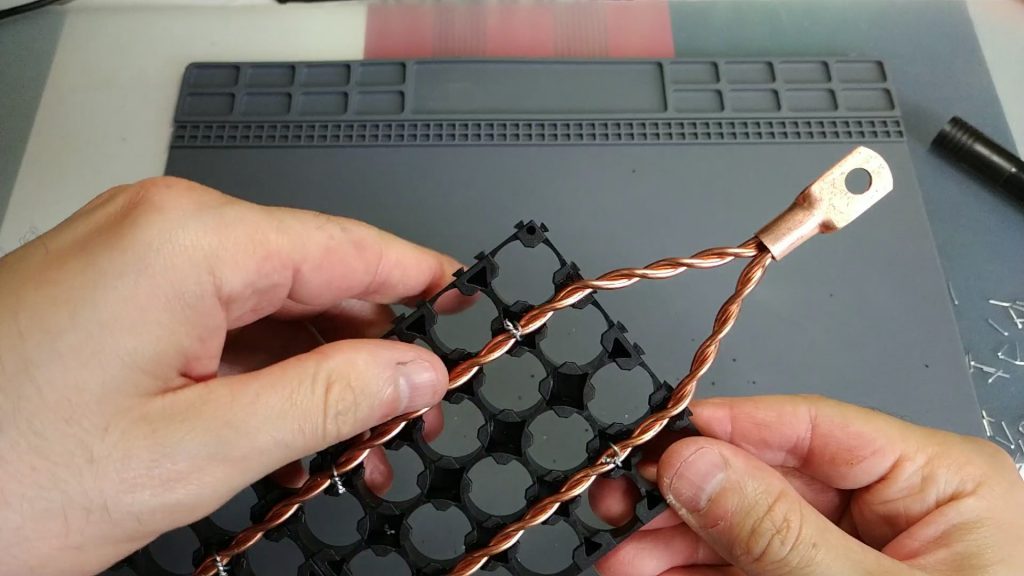
The cell holder measures approx. 30cm. With a 40cm bus bar, we have 5cm left over on each side. The next point is to make a mark with those 5cm, then fold the bus bar with a pliers about 30 degrees. I’ll leave you some pictures:
The next step is to attach the bus bar to the stand. To do this we will use some wires that we will introduce through the holes that we made previously. First let’s prepare the wires. We will cut them into pieces of 6cm approx, and fold them with a pliers making a U-shape to facilitate insertion into the supports:
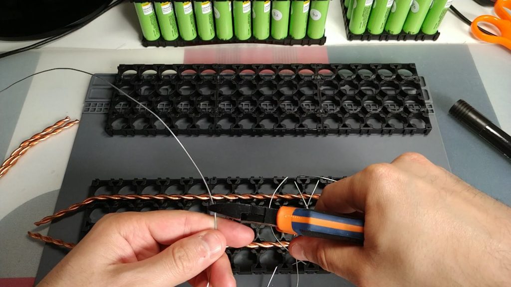
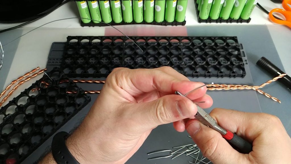
Once the wires are prepared, we will insert them into the supports, in the holes we made earlier, from the inside to the outside of the supports:
Now we’ll fix the bus bar with these wires. First we screw the wires with our hand taking care to leave the bus bar well centered. Once we have it right, we will give it the final tightening with a pliers:

The truth is very very robust. Bus bars don’t move at all. It’s a very good base for welding the cells afterwards.
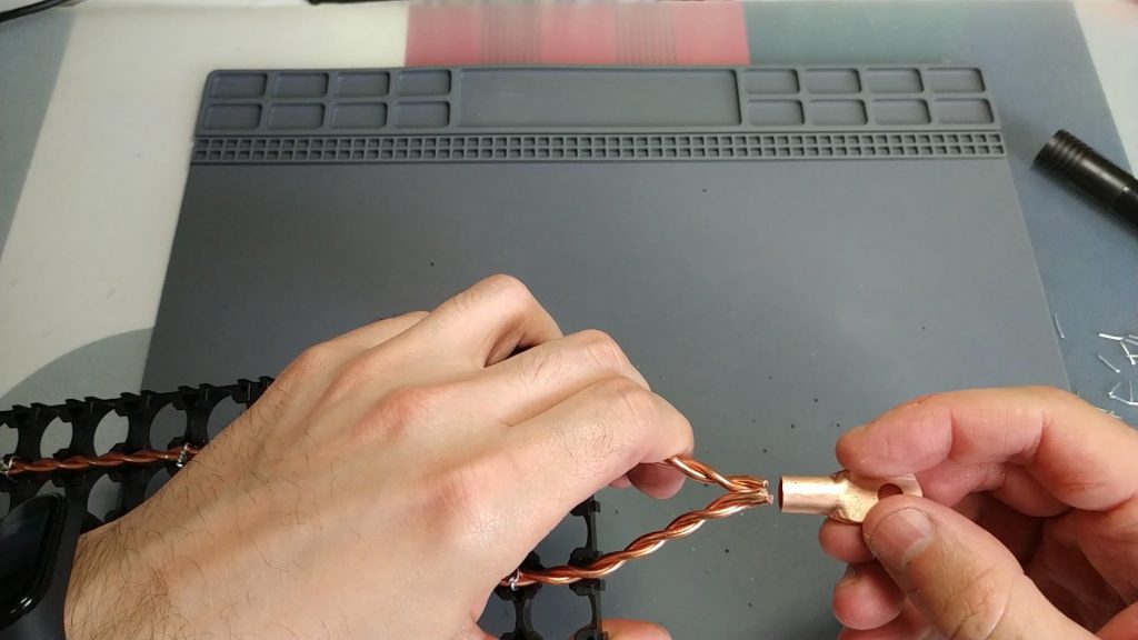
The next step is to add the terminals to the bus bar. In my case I used copper terminals, for 25mm2 cables (it is the model SC25-6). You can buy them at the following link: buy 25mm2 copper terminals
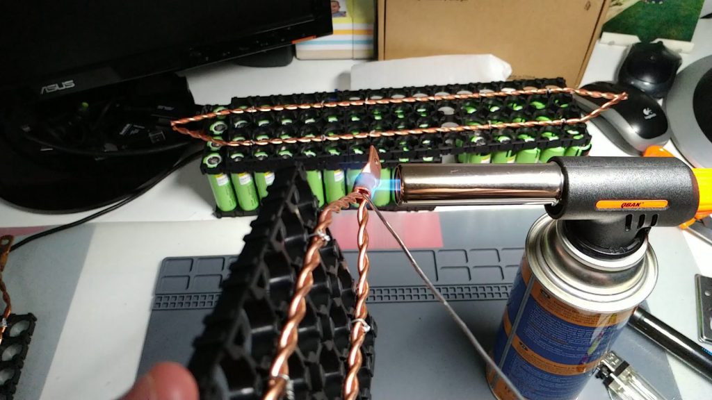
Before putting the terminals in, we must bend the tips a little so that they are more parallel, and enter well into the terminal. We’ll finally tin with the terminals. It is necessary to use a blowtorch, as it is a lot of surface and does not look good if we do it with a normal tin welder. I’ll leave you some pictures:
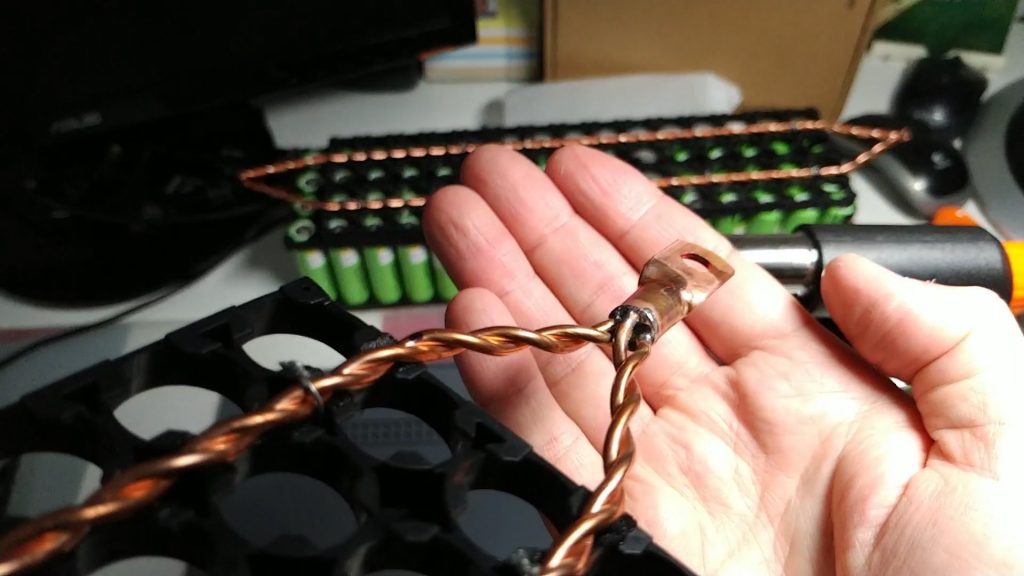
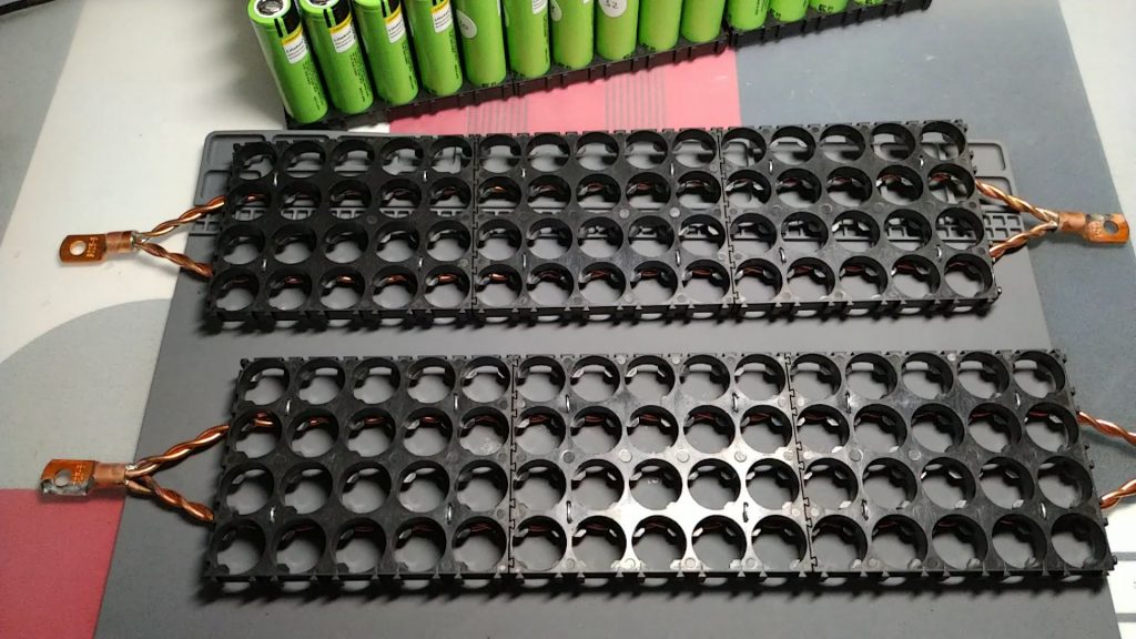
Once this is complete, we have the brackets ready to assemble the cells. It gives some work, but it is worth it, since, as I mentioned above, there are some very robust supports. The bus bar doesn’t move at all.
I’ll leave you a picture with the final result. We have ready the two brackets (top and bottom) to put the cells in:
In the next entry we see how to mount the cells on the brackets, weld them with the fuses and apply the final finish to the pack. You can access the following link: DIY Powerwall (battery pack assembly)
Any questions, leave it in comments.
See you at the next entrance! Best regards!